

Added February 2018
WHEEL QUARTERING
 For many years I have used the tried-
and-tested method of quartering wheels by eye - aligning spokes visually, combined with a bit of trial-and-error. This has worked reasonably well for me for the two dozen locos I have built over the past 40 years or so. From time to time I have thought about buying a wheel quartering jig, but had not found any that appealed.
However, at Scaleforum 2017 I came across G W Models’ quartering jig which seemed to fit what I needed, at a very reasonable price. For me, the jig’s appeal is in its simplicity of concept and robust construction.
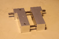
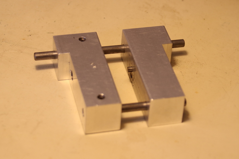
The jig is in two parts, as shown in the photo, left. On each half is a spring-loaded pin on which each wheel is located. Adjacent to the two pins are slots (at 90 degrees to each other) in which the crank pins are located (photo right).
To mount the wheels on the axle, the two wheels are located on their respective pins, with the crank pins in the slots. The axle is located between the wheel centres, and the two halves of the jig are squeezed together. Notwithstanding a few comments on RMWeb, you don’t need three hands, and you don’t need a vice to close the jig for either Sharman or Gibson wheels. As with any method of mounting wheels, the axle ends need to be rounded off slightly to ease the entry of the axle into the wheel boss.
The spring-loaded pins are adjustable, and the instructions suggest that they should be set flush with the surface of the jig when fully depressed, so that the gauge of the wheels is determined entirely by the accuracy of the length of the axle. If the axle is fractionally short, then the wheels will necessarily be undergauge. I take a slightly different approach, and set the pins a few thou proud of the surface of the jig. When the jig is tightly squeezed and held together, the wheel back-to-back can be checked. The wheels are likely to be slightly over-gauge, and by continuing to hold the jig tight, the spring-loaded pins can be backed off a tiny amount to allow the jig to be squeezed a bit further, checking with a B2B gauge, and repeating until the correct B2B is achieved.
As described elsewhere, my split-axle method requires wires to be soldered to the backs of the tyres, and inserted into the wheel boss. To accommodate these I have cut slots in the spring-loaded pins, as shown in the photo.
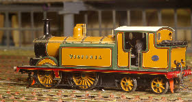
In practice the jig is simple to use, much quicker than my eyeball technique, and more accurate. I’ve used it on all new locos, and have also used it to re-wheel a couple of older engines where the running wasn’t as good as I wanted. It takes me a couple of hours to remove wheels, clean axles and bearings, and to re-assemble a chassis. The improvement in running of these engines has been impressive, so I will work my way through all my engines over the next few months.
WHEEL QUARTERING
 For many years I have used the tried-
However, at Scaleforum 2017 I came across G W Models’ quartering jig which seemed to fit what I needed, at a very reasonable price. For me, the jig’s appeal is in its simplicity of concept and robust construction.
The jig is in two parts, as shown in the photo, left. On each half is a spring-
To mount the wheels on the axle, the two wheels are located on their respective pins, with the crank pins in the slots. The axle is located between the wheel centres, and the two halves of the jig are squeezed together. Notwithstanding a few comments on RMWeb, you don’t need three hands, and you don’t need a vice to close the jig for either Sharman or Gibson wheels. As with any method of mounting wheels, the axle ends need to be rounded off slightly to ease the entry of the axle into the wheel boss.
The spring-
As described elsewhere, my split-
In practice the jig is simple to use, much quicker than my eyeball technique, and more accurate. I’ve used it on all new locos, and have also used it to re-